
One of the most challenging aspects of teaching 3d modeling is to make the students to follow a few guidelines about technical modeling. Most people go straight to what I use to call “artistic modelingâ€, which deals with 3d models only by the way they look, and not how to build them. For instance, in architectural visualization this type of modeling is used to create 3d furniture, using whatever type of edge flow in ply modeling. Then, by the time we have to add some textures with UV’s a big amount of the topology will need a rework, otherwise the UV mapping will demand a lot of manual editing work.
To avoid problems like this in UV mapping is always recommended to follow a few guidelines to organize the edge flow of any model. That’s the reason I always try to use a few diagrams about technical modeling, and make my students follow those diagrams. Last week I just found another one of those useful diagrams about edge flow organization:
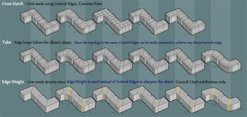
The object of this set of modeling schemes is to show how to create and design the edge flow for corners in 3d modeling.
All diagrams are in Flash format, and when we click over any of those images we will take a closer look for more details in each one of them. For those of you learning to work with technical 3d modeling, I recommend you try those corner modeling schemes. For small scale objects like furniture, they are incredibly helpful.

Very cool!
Thank you very much.
Though im not related to architecture but it sure wud prove to b very helpful